Underfloor Wheel Dropping Machine Locomotive EMU Metro Maintenance Equipment
- Category: Railway Maintenance Workshop Equipment
- Application: rapid wheelset disassembly and assembly machine
- Total installed power:≤25kW
- Rated lifting capacity:30t
- Lifting stroke:1500mm
Underfloor Wheel Dropping Machine Locomotive EMU Metro Maintenance Equipment
1. Brief introduction:
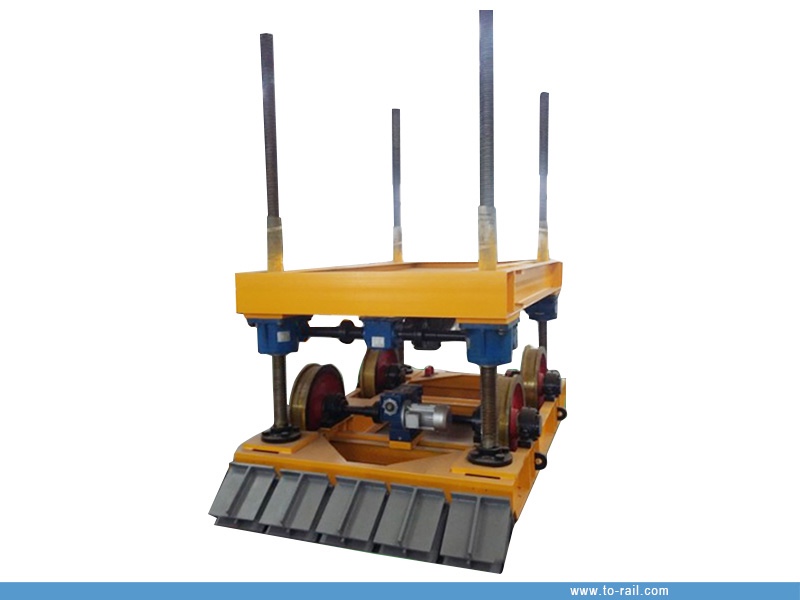
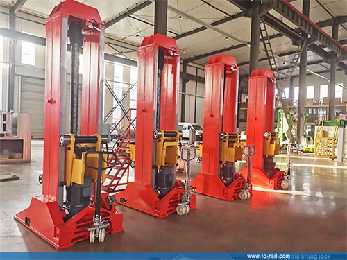
Underfloor wheel dropping machine is ideal for rapid wheelset disassembly and assembly without removing the bogie, widely used in railway rolling stock maintenance depots, EMU and metro vehicle overhaul bases.
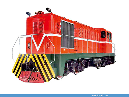
Wheel Dropping Machine is a specialized railway maintenance equipment installed below the rail surface in a foundation pit. It enables fast overall removal and installation of locomotive or vehicle wheelsets without pushing away the bogie, greatly improving maintenance efficiency for wheelset replacement and overhaul.
2. Main technical parameters:
|
Item |
Specification |
|
Power Supply |
380V±10% 50Hz |
|
Total Installed Power |
≤25kW |
|
Rated Lifting Capacity |
30t |
|
Rated Traveling Capacity |
10t |
|
Lifting Stroke |
1500mm |
|
Lifting Speed |
≥0.3m/min |
|
Rail Specification |
50kg/m |
|
Traveling Gauge (in Pit) |
1400mm |
|
Locomotive Running Gauge |
1435mm |
|
Max. Overall Dimension |
3980×2200×3055mm |
3. Main Structure:
The wheel dropping machine is mainly composed of a rail transition bridge, a lifting transmission mechanism, an underframe traveling mechanism, and an electric control system. The transition bridge can be separated from the wheel dropping machine: in normal operation, the pins at both ends of the transition bridge are inserted into the supports on the pit wall, which does not affect the passage of vehicles; however, during the wheel dropping operation, the pins at both ends of the transition bridge must be retracted so that the transition bridge can work together with the lifting platform of the wheel dropping machine.
- Rail Transition Bridge
The rail transition bridge is equipped with movable pins, which adopt a linkage device. One person can operate the push handle to push out both pins at the same time for insertion into the supports on the wall of the wheel dropping pit. A protective device is provided to prevent manual misoperation, and a wheelset positioning device is also installed.
Due to the different structural forms of the bogies of power cars, trailers and control cars, and considering the compatibility of operation requirements, the transition bridge of the wheel dropping machine shall be equipped with two independent movable rails, which form a through connection with the fixed rails at both ends, providing space for the disassembly and assembly of traction rods and the passage of vehicles.
Since the bogies of EMUs are all of two-axle design, it is necessary to consider the auxiliary support of the bogie frame after a single wheelset is dropped. Two sets of movable auxiliary supports shall be provided: the power car is supported at the end of the frame, and the trailer and control car are supported at the middle of the frame. The height of the auxiliary supports can be finely adjusted, which are all applicable to the wheel dropping operation of various types of power-concentrated EMUs.
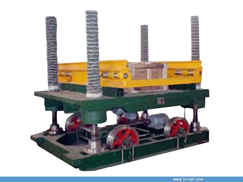
- Lifting Transmission Mechanism
The lifting transmission mechanism is connected to the lead screw of the underframe. Its transmission is connected to the lifting reducer through a reversing gearbox by a double-shaft extension motor. The inside of the lifting reducer is the transmission nut, and the four nuts can drive synchronously to realize the synchronous lifting of the worktable. The lifting is driven by a three-phase asynchronous motor, which allows heavy load and frequent starting of the motor.
A protective cover is installed at the top of the lead screw to prevent foreign objects from falling into the lead screw and the nut. A rubber protective cover is arranged on the lead screw between the lifting platform and the base to prevent dust and debris from entering, so as to extend the service life of the lead screw.
- Under frame Traveling Mechanism
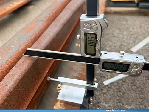
The underframe traveling mechanism is the mechanism for the electric wheel dropping machine to travel on the rail surface in the pit. It drives the driving wheel of the equipment to transmit after being decelerated by the reducer. Limit switches are respectively installed at the joints of the two rails of the electric wheel dropping machine to ensure the accurate alignment of the rails. Rubber buffers are installed at both ends of the rails to prevent collision with the wall during traveling and play a role in protecting the equipment.
- Electric Control System
The electric control system is configured as a control box, which is respectively equipped with buttons such as lifting, lowering, forward, backward, emergency stop and indicator lights to control the actions of the equipment.
The equipment is equipped with a remote controller: it can remotely control the lifting, lowering, forward and backward of the wheel dropping machine, facilitating remote control and adjustment.
4. Safety factors:
(1) The lifting transmission mechanism is equipped with upper and lower limit switches: when the wheel dropping machine rises to the upper limit, it stops rising; when it descends to the lower limit, it stops descending.
(2) The traveling transmission mechanism is equipped with forward and backward limit switches: when the wheel dropping machine moves forward to the forward limit, it stops moving forward; when it moves backward to the backward limit, it stops moving backward.
(3) The equipment is equipped with a drain pump: the start and stop of the drain pump are controlled on the control box.
(4) The equipment is equipped with a reference surface alarm function: an alarm prompt is issued when the equipment reaches the reference surface.
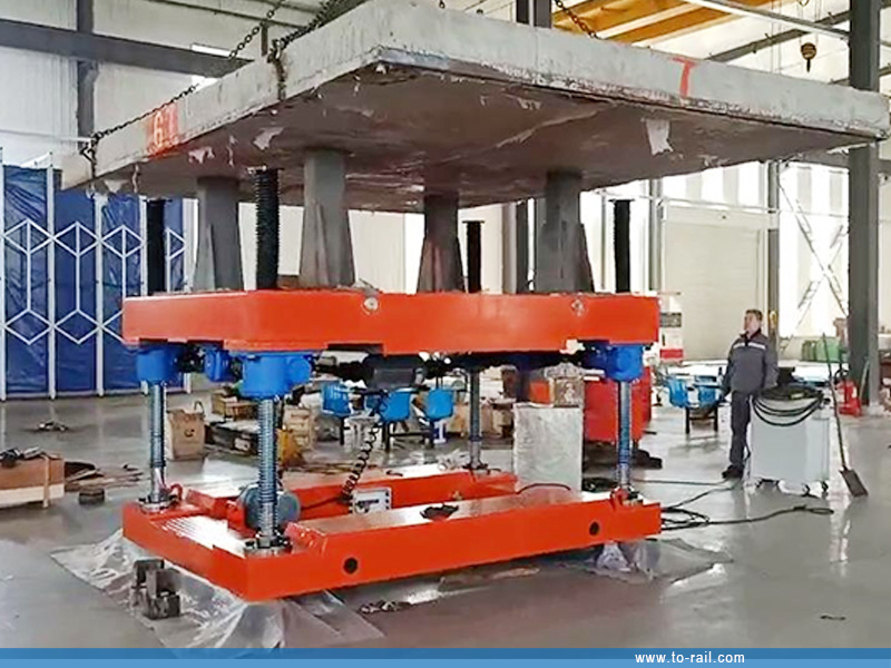
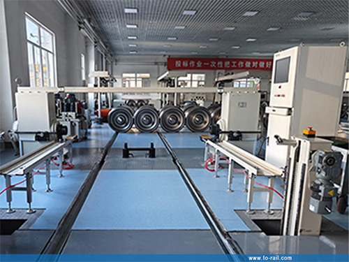
5. Testing in workshop:
INQUIRY
RELATED PRODUCTS
CATEGORIES
CONTACT US
Name: Ms. Zhang
Mobile:+86-13222235952
Whatsapp:+86-13222235952
Email:sales@to-rail.com
Add:Room B1701, Building 4, Dongfang Xintiandi, Yangshe Town, Zhangjiagang, Suzhou City, Jiangsu Province, China